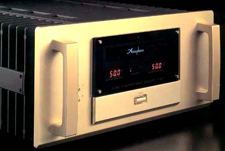
 Class-A Stereo Power Amplifier A-50V Class-A Stereo Power Amplifier A-50V
|
|
|
 Pure class-A drive delivers high-quality power: 50 watts x 2 into 8 ohms Pure class-A drive delivers high-quality power: 50 watts x 2 into 8 ohms |
| Output stage with 10 parallel push-pull power MOS-FETs assures power linearity down to ultra-low impedance load, with 400 watts x 2 into 1 ohm |
| Current feedback circuit topology assures great sound and stable operation |
| Bridged use of two units possible for four times the output power |
| Large toroidal "Super Ring" power transformer |
|
The peerless sound of pure class-A - Power MOS-FETs in the output stage with a 10-parallel push-pull configuration perform extremely low output impedance and realize constant-voltage drive for perfect speaker control. Linear power progression ranges from 50 watts into 8 ohms to 400 watts into 1 ohm in stereo operation. Current feedback circuit topology assures great sound and operation stability.
The mono power amplifier M-2000 was widely acclaimed as an impressive blend of performance and sound quality thanks to the realization of two major principles: very low output impedance (Note 1), and constant drive voltage (Note 2).
The A-50V is a stereo power amplifier based on the same design technology as the M-2000. It uses MOS-FET devices selected for their musical qualities which are driven in a no-holds-barred class-A circuit configuration. The amplifier brings out even the most delicate nuances in the source with full authority. This is Accuphase sound at its very best.
Pure class-A operation means that the circuit always draws the same amount of power from the power supply, regardless of the presence or absence of a music signal. It is impervious against external influences and has high stability. The output stage produces considerable amounts of thermal energy, but in the A-50V this is dissipated by extra-large heat sinks for the left and right channels, to prevent the possibility of problems caused by internal heat buildup.
Current feedback topology ensures good phase characteristics in the upper frequency range, combining operation stability with excellent frequency response. The MOS-FET devices in the output stage are renowned for their high reliability paired with favorable sonic properties. The amplifier has outstanding power linearity realized even at extremely low impedance loads, as illustrated by the power rating that extends from 50 watts into 8 ohms to 400 watts into 1 ohm. The muscle for this kind of performance comes from an ultra-efficient Super Ring type toroidal power transformer of massive proportions, complemented by ample filtering capacity.
Balanced inputs shut out externally induced noise. Gold-plating of circuit traces, input/output connectors, and all other major signal-carrying parts ensures total sonic purity. Bridged operation mode turns the unit into a monaural amplifier with even more power.
Note 1: The reasoning for low amplifier output impedanceThe load of a power amplifier, namely the loud-speaker, generates a counter-electromotive force that can flow back into the amplifier via the NF loop. This phenomenon is influenced by fluctuations in speaker impedance, and interferes with the drive performance of the amplifier. The output impedance of a power amplifier should therefore be made as low as possible by using output devices with high current capability. This absorbs the counter-electromotive force generated by the voice coil and pre-vents the occurrence of intermodulation distortion. Note 2: The constant drive voltage principleEven in the presence of a load with wildly fluctuating impedance, the ideal power amplifier should deliver a constant voltage signal to the load. When the supplied voltage remains constant for any im-pedance, output power will be inversely proportional to the impedance of the load. A conventional amplifier can be easily made to operate in this way down to a load impedance of about 4 ohms. At 1 ohm, however, eight times the output of an 8-ohm load is called for, which can only be sustained by an extremely well designed and capable output stage and a highly robust and powerful power supply section. To build such an amplifier is a task that requires not only considerable experience and resources but also a thorough rethinking of basic principles.
Power MOS-FET output stage in 10-parallel push-pull configuration delivers 400 watts into 1 ohm, 200 watts into 2 ohms, 100 watts into 4 ohms, or 50 watts into 8 ohms with outstanding linearity The output stage uses power MOS-FETs with negative thermal characteris-tics. 10 pairs of these devices are arranged in a parallel push-pull configuration for each chan-nel. The result is stable operation with ideal power linearity even at ultra-low impedance load. The maximum power dissipation of one MOS-FET is 120 watts, but the actual power load per pair is only 5 watts, so that each de-vice is driven only in its low-power range where linearity is excellent. The drive stage also uses power MOS-FETs, in a cascode connection that gives wide frequency response and requires only small amounts of negative feedback. This also contributes to sound quality. Figure 2 shows the output voltage/current characteristics at various impedance loads. Output voltage is almost constant at various loads, which means that current increases linearly.

Figure 2
|
Current feedback topology prevents phase shifts
The amplifying circuits in the A-50V use the current feedback principle
for negative feedback. At the input point of the feedback loop, the im-pedance
is kept low and current detection is performed. A trans-impedance amplifier
then converts the current into a voltage to be used as the feedback signal.
Since the impedance at the current feedback point (current adder in Fig-ure
3) is very low, there is almost no phase shift. Phase compensation therefore
can be kept at a minimum. |

Figure 3
|

Figure 4
|
A minimal amount of NFB results in Bridged operation mode creates a true
monophonic amplifier with 800 watts into 2 ohms, 400 watts into 4 ohms,
or 200 watts into 8 ohms.
Bridged mode means that the two channels of an amplifier are driven with
the same signal volt- maximum improvement of circuit parameters. The result
is excellent transient response and superb sonic transparency, coupled
with utterly natural energy balance. Figure 4 shows frequency response
for different gain settings of the current feedback amplifier. The graphs
demonstrate that response remains uniform over a wide range. age but with
opposite phase, and their output is combined. The A-50V provides a switch
arrangement for bridged operation, which turns the unit into a high-grade
monaural amplifier capable of delivering even more stunning amounts of
power.
|
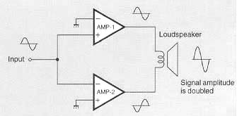
Figure 5
|

Switch
|
Balanced connection reliably blocks induced noise.
The balanced connection principle makes use of the fact that induced noise
in two cable leads will be of the same phase. By combining the signals
at the receiving end, the noise is canceled out and only the pure signal
remains. The longer the cable connections between audio components, the
greater is the danger of external noise being introduced into the signal
path. Balanced connection keeps the signal transfer completely free from
any kind of interference. All signal paths gold-platedHigh-purity copper
is commonly used in audio components for signal path lines. The A-50V goes
one step further by providing gold-plating for printed circuit board traces
as well as for the input jacks and speaker terminals. This ap-proach results
in a distinct sonic improvement. Extra-large speaker terminalsThe oversize
speaker terminals accommodate even very heavy-gauge speaker cable. The
ter-minals are made of extruded high-purity brass and are gold-plated for
utmost reliability and minimum contact resistance. Molded caps are provided
to assure proper insulation. Robust power supply with aluminum enclosed
"Super Ring" toroidal transformer and high filtering capacity
|

Troidal transformer , Aluminum electrolytic capacitors
|
The power supply section is a critical aspect of any power amplifier. The A-50V features a large toroidal power transformer with a rating of 1,000 VA. The transformer is housed in a non-resonant aluminum enclosure filled with damping material that has excellent heat transfer characteristics. Toroidal transformers which use heavy-gauge copper wiring on a ring-shaped core have various advantages, such as very low impedance, small size, and high conversion efficiency. The "Super Ring" type transformer used by Accuphase is ideally suited for audio applications. It has the following characteristics: 1. Near-circular core caliber allows near-circular coil windings with high packing density, resulting in low leakage flux and minimum vibrations.
2. Smaller ferrite core diameter and copper windings with high specific gravity mean low ferrite losses and low inrush current.
Two extra-large 82,000 micro F aluminum electrolytic capacitors provide more than ample power supply capacity.
Digital power meter shows true output levelsOutput power is indicated by a digital meter. The meter circuit senses the actual voltage and current levels delivered to the speaker. An analog multiplier circuit calculates the power for any given moment, which is then precisely displayed on the digital meter. Since the level of a musical signal normally fluctuates rapidly, power output would be difficult to read precisely with an analog meter. The digital circuit also takes the complex speaker impedance into consideration, providing an indication of true power at any time.
The hold time of the display can be switched between 1 second and infinite. When the power indication is not required, the meters can also be switched off.
|

Assembly with protection circuitry etc.
|

Digital power meter
|
* Guaranteed specifications are measured according to EIA
standard RS-490.

* Specifications and design subject to change without notice for improvements.
|
|
|
|
|
|
|
|
