 Stereo Control Center C-265 Stereo Control Center C-265
|
|
|
 Line amplifier using current feedback topology for outstanding operation
stability Line amplifier using current feedback topology for outstanding operation
stability |
| Balanced output stage with bridged feedback |
| Fully modular construction with separate amplifier stages |
| Option board allows analog disc playback |
| Logic-controlled relays for shortest signal paths |
| Balanced inputs |
| Supplied remote commander |
|
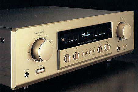
The C-265 is a stereo control center designed for impeccable sound quality.
It incorporates a wealth of prestigious Accuphase technology, such as balanced
signal transmission and current feedback line amplifier stages. In its
standard configuration, the C-265 offers a versatile array of line-level
inputs, but by installing the optional analog disc board in a dedicated
slot on the rear panel, which offers outstanding analog disc reproduction.
In order to bring out the best in program sources and to
extract the full sonic potential of the power amplifier, a preamplifier must
faithfully transmit the music signal without deterioration or sddition of any
form of coloration.
The C-265 achieves this task admirably, thanks to its balanced circuit
topology that reliably eliminates all noise. The output stage is especially
noteworthy for its symmetrically bridged feedback, which results in a floating
design where the signal is kept entirely separate from the ground line.
The line amplifiers are based on the current feedback principle which has
proven its sonic excellence in many top-grade components from Accuphase.
This principle virtually eliminates phase shifts in the upper frequency
range. Frequency response is not affected by gain, and only small amounts
of NFB are required. This allows the phase compensation circuitry to be
kept simple, thus assuring superb transient response.
The C-265 employs modular construction using sturdy enclosures made from
extruded aluminum. This design provides electrical insulation and protects
the amplifier against vibrations and other adverse mechanical influences.
Not only the unit amplifiers, but also the power transformers and filtering
capacitors are kept separate for the left and right channels. This dual
mono configuration precludes any possibility of unwanted electrical interaction.
Tone controls and a loudness compensator allow sonic touch-ups. Balanced
inputs and logical relays ensure extremely short and highly pure signal
paths. The C-265 offers a perfect blend of sound quality and performance
at the highest level.Current Feedback Topology in Line Amplifiers Prevents
Phase ShiftsIn order to improve the characteristics of an amplifier, a
commonly employed technique called negative feedback (NFB) routes part
of the output signal back to the input. Conventional amplifiers employ
voltage NFB, but the C-265 uses the signal current rather than the voltage
for feedback. Figure 2 shows the operating principle of this circuit. At
the sensing point of the feedback loop, current detection with low impedance
is performed. A trans-impedance amplifier then converts the current into
a voltage to be used as the feedback signal. Since the impedance at the
current feedback point (current adder in Fig. 2) is very low, there is
almost no phase shift. Phase compensation therefore can be kept at a minimum,
resulting in excellent transient response and natural energy balance.
Figure 3 shows frequency response for different gain settings of the
current feedback amplifier. With this circuit, there is virtually no change in
frequency response when gain is altered, and response remains uniform over a
wide range.
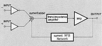
Figure 2
|
|
Balanced Output Stage With Bridged Feedback
In balanced signal transmission, two identical signals are transmitted
simultaneously with inverted phase and combined at the receiving end, thereby
canceling out common-mode noise and interference. This assures pure high-quality
signal transmission. The principle of balanced sound transmission is shown
in Figure 4. The outputs of the two amplifiers AMP1 and AMP2 are connected
to form a cross-feedback loop, which sends the symmetrical (+) and (-)
signals with low impedance to the next stage. The signals are isolated
from the ground line, resulting in an ideal balanced circuit. Even if one
side of the output is grounded, both amplifiers continue to operate, and
the output voltage does not change.
|
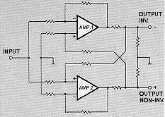
Figure 4
|
|
Discrete Line Amplifier Designed for Sound Quality
The line amplifier (Fig. 5) is a pure complementary push-pull circuit built
from discrete components and employing current feedback. Phase compensation
can be kept to a minimum, resulting in life-like ambience. A balanced input
stage with gain is located directly before the volume control, followed
by the line amplifier. This assures outstanding signal-to-noise ratio also
at low listening levels.
|
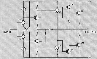
Figure 5
|
|
Fully Modular Construction
The C-265 contains a total of six separate modules comprising the balanced
input amplifiers, line amplifiers, and balanced output amplifiers for each
channel. Mounted on a massive chassis made of extruded aluminum, the modules
provide optimum operating conditions for each circuit segment and reliably
shut out external vibrations.
Separate Transformers for Left and Right Channels and Dedicated Power Supply
Circuits for Each Unit Amplifier
Two completely separate sets of transformers and filtering capacitors are
provided, to preclude any possibility of electrical interaction between
the channels. In addition, each unit amplifier has its own wide-range voltage
regulator circuitry, to eliminate possible interference between stages.
Logic-Controlled Relays Assure High Sound Quality and Long-Term Reliability
To realize the shortest possible signal paths, the C-265 employs logic-controlled
high-quality relays strategically placed near the signal entry and exit
points. The relays are high-quality types originally developed for professional
communication applications. Their gold-plated cross-bar twin contacts ensure
minimum contact resistance and outstanding long-term reliability.
Tone Controls Use Summing Active Filters for Highest Sound Quality
The tone control circuitry in the C-265 was specially designed with summing
active filters such as found in high-quality graphic equalizers. Figure
6 illustrates the operation principle of this circuit. The flat signal
is passed straight through, and only when an adjustment is required, the
characteristics are created at F1 and F2 and added to the signal, thereby
producing the desired change. This design provides efficient control without
degrading signal purity.
|
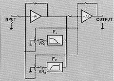
Figure 6
|
|
Dedicated Headphone Amplifier for Optimum Sound
The C-265 provides a separate amplifier for the phone jack designed to
provide superior sonic performance. The power amplifier output can be cut
off by a switch, and the main volume control can be used to adjust the
headphone listening level.
Versatile Input Configuration Including Balanced Inputs
The input selector has eight positions (including positions for two optional
inputs), and two tape recorders can be connected to the C-265. Two inputs
(CD and LINE) offer balanced connectors, for high-quality signal transmission
free from externally induced noise.
High-Quality Volume Control and Supplied Remote Commander for Source Switching
and Volume Level Adjustment
The volume control is a vital element in a preamplifier which has an important
bearing on the sonic result. The C-265 uses a top-grade device with special
low-distortion resistors. When the supplied remote commander is used to
adjust the listening level from a distance, a small motor drives the volume
control via a clutch, for smooth, reliable action.
|
Options
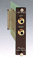
LINE-10 |
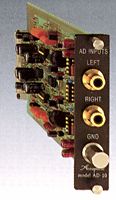
AD-10 |
|
|
* Guaranteed specifications are measured according to EIA
standard RS-490.
* Specifications and design subject to change without notice for improvements.
|
|
|
|
|
|
|
|
