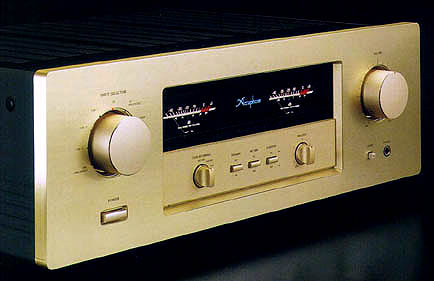
 Integrated Stereo Amplifier E-306 Integrated Stereo Amplifier E-306
|
|
|
Current feedback circuit topology assures excellent transient response
and superb sonic realism. parallel push-pull output stage delivers a full
100 watts/ch of quality power into 8 ohms. Highperformance phono equalizer
accommodates MM and MC cartridges. Logic-controlled relays assure reliable
source switching
|
|
|
An integrated amplifier, as the name implies, combines a preamplifier and a power amplifier in a single chassis. The preamplifier handles extremely low-level signals, whereas the power amplifier has to deal with high currents. This means that overall gain is extremely high, and even the slightest interference or crosstalk at the input can have a considerable effect on the sonic result. To preclude this possibility, the E-306 is designed to achieve total electrical and structural separation of the two sections. This integrated amplifier opens up a new chapter in music reproduction, offering sound quality that rivals some of the best separate components.
An importantfeature of the E-306 is the use of current feedback circuit
topology in the power amplifier. This principle developed by Accuphase
virtually eliminates phase shifts in the upper frequency range and assures
uniform frequency response which does not change with gain. In other words,
it combines total operation stability with excellent frequency response.
Thanks to this principk), phase compensation can be kept at a minimum,
and high amounts of negative feedback with their associated disadvantages
are no longer required. This assures excellent transient response, with
superb sonic transparency and detail. Music reproduced by the E-306 sounds
uncannily real.
The preamplifier section incorporates a high-quality discrete-type line amplifier and a phono equalizer for reproduction of analog discs, using MM or MC cartridges. All parts and circuit components of the E-306 have been strictly selected for sonic purity. A versatile complement of nine inputs including two balanced inputs can accommodate a wide variety oT program sources. All switching is performed by logic-controlled hermetically sealed relays with gold contacts. A supplied remote commander lets you adjust the volume and select input sources from anywhere in the listening room. In the interest of assuring top-quality sound, the number of features has been limited to include only truly essential and useful functions. The simple, uncluttered design in the Accuphase tradition makes the E-306 a joy not only for the ears but for the eyes as well.
Parallel push-pull output stage delivers quality power: 140 watts/channel
into 4 ohms, 120 watts/channel into 6 ohms or 100 watts/channel into 8
ohms
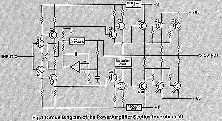
Figure 1 shows a circuit diagram of the power amplilication stage. The
power transistors are designed for audio applications and have been selected
for optimum frequency response, forwardcurrent transfer ratio linearity,
and switching performance characteristics. By mounting the devices to a
large heat sink and connecting them in parallel, the E-306 achieves ample
power output capabilities, providing a 140 watts into 4 ohms, 120 watts
into 6 ohms, or loo watts into 8 ohms per channel.
|
|
|
Current feedback circuit topology prevents phase shifts
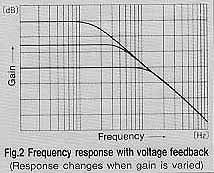
When the gain of an amplifying circuit increases, frequency response, i.e.
the bandwidth that can be handled by the amplifier, becomes more narrow.
To counter this effect, a commonly employed technique called negative feedback
(NFB) routes part of the output signal back to the input. If phase shift
is disregarded, a circuit designed to have high open-loop-gain can apply
a high amount of NFB, resulting in the wide frequency response of a closed
hoop circuit, as shown in Figure 2.
|
|
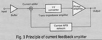
Conventional amplifiers employ voltage NFB, whereby the output voltage
is used for the feedback loop.ln the E-306 however, the signal current
rather than the voltage is used for feedback. Figure 3 shows the operating
principle of this circuit. At the sensing point of the feedback loop, the
impedance is kept how and current detection is performed. An impedance-converting
amplifier then converts the currant into a voltage to be used as the feedback
signal. Since the impedance at the current feedback point (current adderin
Fig. 3) is very low, there is almost no phase shift. Phase compensation
therefore can be kept to a minimum, resulting in excellent transient response
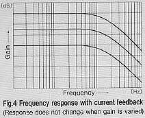
and superb sonic transparency. Figure 4 shows frequency response for different
gain settings of the current feedback amplifier. The graphs demonstrate
that response remains uniform over a wide range
|
|
|
Robust power supply with large power transformer and high filtering capacity
The power supply plays a vital role as the source of energy for the power
amplifier section. The E-306 spares no efforts n this regard, featuring
a large 500 VA power transformer and two large electrolytic capacitors
rated for 22,000 micro F each. This assures ample reserves also for reproduction
of demanding bass passages.
Discrete-type tine amplifier for superior sonic purity
The line amplifier whose circuit diagram is shown in Figure 5 is entirely
built from discrete parts, to assure optimum performance. Circuit design
is based on the differential pure complementary push-pull principle developed
by Accuphase, white the output stage is a single-ended push-pull emitter
follower. This comparatively simple circuit topology requires only minimal
amounts of phase compensation in each stage, which enhances signal purity
and results in effortless, utterly natural sound.
High-quality phone equalizer stage accommol dates MM and MC cartridges
The E-306incorporates a high-performance phono stage (Fig.6) designed to
enable top-notch repro- duction of your vaLuable analog records. Separate
input circuits are provided for moving-coil (MC) and moving-magnet (MM)
cartridges, to fully bring out the advantages of each cartridge type.
Since MM cartridges have high output voltage as well as high output impedance,
the FET input stage is designed to maintain high input impedance over the
entire frequency range. On the other hand, the MC section has to deaL with
very low-level signals at low impedances. Therefore, two low-noise devices
are arranged in a differential configuration with a low-impedance NFB loop,
to assure optimum signal-to-noise ratio and keep residual noise at a minimum.
Highly reliable logic-controlled relays
Long signal paths for functions such as input switching and tape monitoring
tend to degrade high-frequency response and impair imaging. ln the E-306,
all switching is performed by logic-controlled relays which are arranged
so as to permit the shortest possible signal paths. The hermetically sealed
relays are high quality types developed specifically for demanding communication
applications. The contacts are twin crossbar types plated with gold for
minimum contact resistance and outstanding long-term reliability.
Versatile input configuration including balanced connectors
In order to accommodate the ever increasing variety of program sources,
the E-306 offers eight inputs controlled by the input selector plus another
input for a tape recorder. Two of these inputs are designed for balanced
connections. The principle of balanced signal transmission is shown in
Figure 7. At the source component, the signal is converted into a positive
and negative signal with identical voltage potential but phase-inverted
by 180 degrees. The receiving equipment precisely combines the two signals.
Since any noise which was picked up by the connecting cable etc. has the
same phase in both lines, it is canceled by the mixing process, ensuring
noise-free signal transmission with optimum sonic purity.
Remote commander allows source switching and volume adjustment
Listening level adjustment is performed by a small motor which drives the
volume control via a clutch, for smooth, reliable action. The input selector
controls the relays in the E-306, offering remote control convenience without
any sacrifices in sound quality
Independent use of preamplifier and power amplifier possible
Separate outputs and inputs controlled by a selector switch allow use of
the preamplifier section and the power amplifier section as separate components.
Large, direct-reading peak power meters
The large analog power meters have a peak holdb function which lets you
easily monitor the output level of the rapidly fluctuating music signal.
Thanks to logarithmic compression, the meters cover a wide dynamic range.
Heavy-duty speaker terminals accommodate also barlana Plugs
The oversize speaker terminals accept even very heavy-gauge speaker cable,
and it is also possible to insert banana plugs.
|
|
|
|
|
|
|
|
