 Monophonic Power Amplifier M-2000 Monophonic Power Amplifier M-2000
|
|
|
 Ultra-powerful output stage with 22 parallel push-pull transistors delivers
250W into 8 ohms, and remains linear down to extremely low impedance (2,000W
into 1ohm) Ultra-powerful output stage with 22 parallel push-pull transistors delivers
250W into 8 ohms, and remains linear down to extremely low impedance (2,000W
into 1ohm) |
| Current feedback circuit topology assures great sound and stable operation |
| Bridged use of two units possible for times the output power operation |
| Large toroidal power transformer rated for 1.5kVA |
| Balanced inputs |
|
|
The impedance of a loudspeaker often fluctuates drastically depending on
the music signal that is being supplied. Sometimes impedance can drop to
very low levels, especially in many high-end models. In order to tame this
extreme fluctuation and showcase the best sonic characteristics of a speaker,
the amplifier must have very low output impedance (Note 1), and it must
be able to supply a constant drive voltage (Note 2).
When an amplifier is designed to cope with low load impedances, this also means that it will be fully able to absorb the counterelectromotive force generated by the voice coil, thereby preventing the occurrence of intermodulation distortion.
The Accuphase M-2000 was designed to realize the ideal of constant voltage
drive. This no-compromise approach inevitably resulted in a single-channel
monaural unit.
A complement of 22 output transistors with a collector dissipation (Pc)
of 130 watts each is used in the output stage. Connected in parallel, these
devices have a combined collector dissipation of 5,700 watts. At the extremely
low load impedance of 1 ohm, the amplifier is rated to deliver 2,000 watts
(actual measurement 2,370 W).
The output rating into 2 ohms is 1,000 watts (actual measurement 1,570
W), and into 4 ohms 500 watts (actual measurement 890 W). This progression
demonstrates the amazing linearity of the amplifier which is close to the
absolute ideal. The top-notch level of performance is sustained by no-holds-barred
construction, including a massive Super Ring toroidal transformer (rated
for 1,500 VA, max. 3,000 VA) housed in a diecast enclosure with directly
mounted heat sinks, and serviced by two extra-large filtering capacitors
with a capacity of 40,000 uF each.
This assures more than ample reserves and allows the M-2000 to meet even
the most demanding and rapidly fluctuating power requirements.
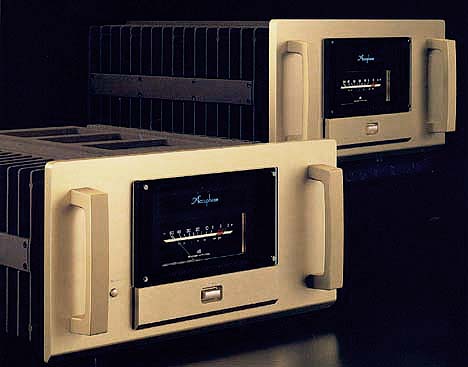
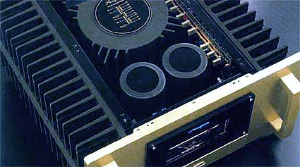
The massive aluminum diecast heat sinks at the right and left of the amplifier achieve highly efficient dissipation of thermal energy. Together with the front panel, chassis, and rear panel, they form an extremely strong and sturdy entity.
A large analog power meter located in the center of the front panel provides
useful information, and the faceplate in traditional Accuphase brushed
gold aluminum blends favorably with the decor of any listening room. Besides
being a joy to behold, the M-2000 of course sounds absolutely stunning.
It handles the entire dynamic spectrum from fortissimo to pianissimo with
ease and authority, letting the music emerge as never heard before.
|
The reasoning for low amplifier output impedance
The load of a power amplifier is the loudspeaker which generates a counterelectromotive
force that can flow back into the amplifier via the NF loop. The signal
fed back in this way is influenced by fluctuations in speaker impedance,
and interferes with the drive performance of the amplifier. The output
impedance of a power amplifier should therefore be made as low as possible
by using output devices with high current capability
|
The constant drive voltage principle
Even in the presence of a load with wildly fluctuating impedance, the ideal
power amplifier should deliver a constant voltage signal to the load. When
the supplied voltage remains constant for any impedance, the output power
will be inversely proportional to the impedance of the load. A conventional
amplifier can be easily made to operate in this way down to a load impedance
of about 4 ohms. In the region from 3 to 2 ohms, an increase in thermal
energy becomes a problem and can lead to the destruction of the output
transistors. At 1 ohm, eight times the output of an 8-ohm load is called
for, which can only be sustained by an extremely well designed and capable
output stage and a highly robust and powerful power supply section. To
build such an amplifier is a task that requires not only considerable experience
and resources but also a thorough reevaluation of basic principles.
|
|
1. Ultra-powerful output stage with 22 parallel push-pull transistors delivers
2,000 watts into 1 ohm, 1,000 watts into 2 ohms, 500 watts into 4 ohms
and 250 watts into 8 ohms
TheM-2000 uses a complement of 22 high-power transistors with a collector
dissipation (Pc) of 130 watts and a collector current of 15 A each. These
devices are excellent in every regard, including frequency response, current
amplification linearity, and switching characteristics. Because the 22
devices are connected in a parallel push-pull configuration, the output
stage has extremely low impedance. Since the devices are directly mounted
to the extra-large aluminum diecast heat sinks, heat produced during operation
is dissipated with high efficiency. As a result of this no-compromise design
with a high performance margin, the power amplifier is capable of delivering
enormous output power in a linear progression towards lower load impedances.
It also is able to drive reactive loads with ease.
Figure 1 is a graph plotting the output voltage versus current characteristics, based on actual measurements for various load impedances. Thanks to the extremely low impedance of the output stage, the output voltage remains approximately constant also when the load changes, and only the current increases, as is clearly evident from the chart. This demonstrates the advanced performance of the constant voltage drive.
|
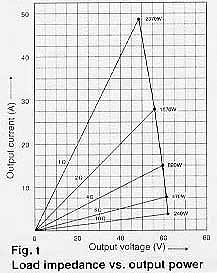
Figure 1
|
Parallel connection of output devices
Semiconductor devices for high-frequency applications often use the multi-chip
principle where many small transistors or FETs are internally connected
in parallel. This reduces internal noise and the internal impedance of
the device. It also results in a larger surface area of the chip, allowing
the heat to disperse more easily. This in turn contributes to operation
stability. The M-2000 is based on a similar principle. By using multiple
devices connected in parallel, current load is distributed. Signal attacks
and transients which require a high amount of current to be available almost
immediately can be handled with ease. But parallel connection in an Accuphase
amplifier means more than simply stringing together a number of devices.
Various sophisticated techniques are used to accommodate temperature characteristics
and to optimize the current flow pattern. As a result, distortion at low
current levels is improved, and signal-to-noise ratio is outstanding, assuring
impressive dynamic range and sonic transparency. Ample current capability
makes it possible for the amplifier to drive even extremely low loads with
ease.
|
2. Current feedback circuit topology prevents phase shifts
Negative feedback (NFB) is a commonly employed technique in conventional
amplification circuits, routing part of the output signal voltage back
to the input. In the M-2000, the signal current rather than the voltage
is used for feedback. Figure 2 shows the operating principle of this circuit.
At the sensing point of the feedback loop, the impedance is kept low and
current detection is performed. An impedance-converting amplifier then
converts the current into a voltage to be used as the feedback signal.
Since the impedance at the current feedback point (current adder in Figure
2) is very low, there is almost no phase shift. Phase compensation can
be kept to a minimum, resulting in excellent transient response and superb
sonic transparency. Figure 3 shows frequency response for different gain
settings of the current feedback amplifier. The graphs demonstrate that
response remains uniform over a wide range.
|
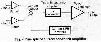
Figure 2
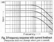
Figure 3
|
|
3. Use of two M-2000 in bridged configuration possible, resulting in a
mono amplifier with four times the power
Bridged operation means that two amplifiers are driven by the same signal
voltage but with opposite phase. The speaker load is then connected between
the positive output terminals of the amplifiers. This results in a fourfold
increase in output power. When used in a bridged configuration, two M-2000
units form a single mono amplifier with awesome power capabilities: 4,000
watts into 2 ohms, 2,000 watts into 4 ohms, or 1,000 watts into 8 ohms.
|
|
4. Balanced connection blocks induced noise
Balanced signal transmission means that two signal lines are used which
carry the same signal with opposite phase. On the receiving side, the signals
are mixed. Since any noise interference that has arisen during transmission
will be present in both lines with identical phase, such noise is canceled
out, leaving only the pure original signal. Balanced connection therefore
keeps the signal transfer free from any kind of interference.
|
|
5. Phase switching without sound quality degradation
A switch is provided which allows inverting the overall phase of the entire
component. Switching is performed by changing the (+) (-) assignment of
the balanced amplifier, thereby avoiding the sound quality degradation
associated with conventional switching methods.
|
|
6. All major signal path components are gold-plated
High-purity copper is commonly being used in audio components for signal
leads and traces. The M-2000 does this one better, by providing gold-plating
for all parts carrying the audio signal. This includes not only the copper
traces on printed circuit boards but extends even to ground bars carrying
large ripple currents, capacitor bus bars, input jacks, and speaker terminals.
|

|
|
7. Robust power supply with "Super Ring" toroidal transformer
and high filtering capacity
The power supply section is a critical aspect of any power amplifier. The
M-2000 features a large toroidal power transformer with a rating of 1.5
kVA. The transformer is housed in a non-resonant aluminum enclosure filled
with damping material that has excellent heat transfer characteristics.
Toroidal transformers which use heavy-gauge copper wiring on a ring-shaped
core have various advantages, such as very low impedance, small size, and
high conversion efficiency. The "Super Ring" type transformer
used by Accuphase is ideally suited for audio applications. It has the
following characteristics:(1) Near-circular core caliber allows near-circular
coil windings with high packing density, resulting in low leakage flux
and minimum vibrations.
(2) Smaller ferrite core diameter and copper windings with high specific gravity mean low ferrite losses and low inrush current.
|

|
|
8. Large, direct-reading analog power meter
The large analog power meter has a peak hold function which lets the user
easily monitor the output level of the rapidly fluctuating music signal.
Thanks to logarithmic compression, the meter covers a wide dynamic range.
An on/off switch controls meter operation and illumination.
|
|
|
* Guaranteed specifications are measured according to EIA standard RS-490.

* Specifications and design subject to change without notice for improvements. |
|
|
|
|
|
|
|
