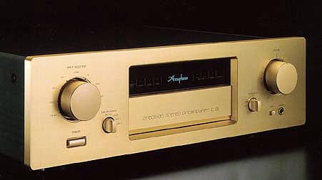
 Precision Stereo Preamplifier C-275 Precision Stereo Preamplifier C-275
|
|
|
 Ideal balanced line amplifier principle Ideal balanced line amplifier principle |
| Current feedback topology for superior operation stability |
| Complete mono construction with separate left/right transformers |
| Logic-control relays for shortest signal paths |
| Dedicated headphone amplifier designed for top-quality sound |
| Supplied remote commander |
|
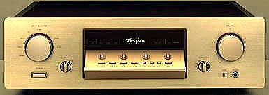
Subpanel contents
Compensator Selector
The compensator circuit restores the natural frequency balance when listening
at low levels. As the human ear becomes less sensitive for the frequency
extremes with decreasing loudness, the sound often seems to be lacking
in bass and treble at low listening levels.
* The degree of loudness compensation is not affected by the setting of the volume control.
Output On/Off Switch
This switch controls the signal at the output jacks. When wishing to listen
with headphones only, set the switch to OFF.
Tone Control On/Off Switch
This switch activates the BASS and TREBLE controls.
* When the switch is set to OFF, frequency response will be flat, regardless of the setting of the BASS and TREBLE controls.
Bass Control
Turning this control to the right from the center (0) position boosts the lower frequency range and turning the control to the left attenuates it.
Treble Control
Turning this control to the right from the center (0) position boosts the upper frequency range and turning the control to the left attenuates it.
Balance Control
This control serves to adjust the left/right stereo balance.
Compensator On/Off
Switch Setting this switch to ON enables the loudness compensation as selected
with the COMPENSATOR selector
Front panel contents
Attenuator Switch This switch serves to quickly reduce the output level of the amplifier. The attenuation level can be selected in three steps: -6 dB, -20 dB, and -30 dB.
Headphone Output Jack
A pair of stereo headphones can be connected to this jack.
* When wishing to listen with headphones only, set the OUTPUTS switch to OFF.
* Control the listening volume with the main volume control.
* Use headphones with an impedance of 4 - 100 ohms.
Tape Recorder Switch
Selectable TAPE 1/TAPE 2 and Recording output ON/OFF
|
|
Balanced Output Stage With Bridged Feedback
In balanced signal transmission, two identical signals are transmitted
simultaneously with inverted phase and combined at the receiving end, thereby
canceling out common-mode noise and interference. This assures pure high-quality
signal transmission. The principle of balanced sound transmission is shown
in Figure 4. The outputs of the two amplifiers AMP1 and AMP2 are connected
to form a cross-feedback loop, which sends the symmetrical (+) and (-)
signals with low impedance to the next stage. The signals are isolated
from the ground line, resulting in an ideal balanced circuit. Even if one
side of the output is grounded, both amplifiers continue to operate, and
the output voltage does not change.
|
|
Optional Analog disk equalizer amplifier AD-275
|
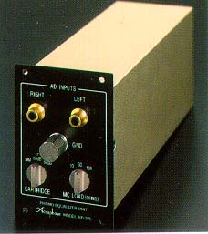
AD-275
|
|
Equalizer Gain Selector This selector determines the gain of the phono equalizer for playback of analog records.
MM
Use this position for MM (moving-magnet) cartridges. The input impedance is 47 kilohms.MC/60dB, MC/66dBUse these positions for low-output MC (moving-coil) cartridges. Select the "MC/60dB" or "MC/66dB" position, depending on the output rating of the cartridge.
* If the MC position is selected while an MM cartridge is connected, level overload and impedance mismatching will lead to dull, distorted sound.
* When using an MC cartridge, select the load impedance after choosing the MC position.
* When switching to a different gain setting and leaving the volume control unchanged, an increase in noise level may be perceived with high-efficiency speakers during pauses in the music or when no input signal is present. This is due to the fact that the overall gain has increased while the inherent noise level of the amplifier remains constant.
* When this selector is operated while the "AD" input position is selected, a muting circuit cuts off the sound for about one second.
MC Cartridge Load Impedance Selector
This switch serves to set the input impedance of the phono stage to match the rated impedance of the MC cartridge.
Normally, the appropriate settings should be chosen according to the following guidelines.
Cartridges rated for more than 20 ohms: "100" _ position
Cartridges rated for 20 ohms or less: "30" or "10" _ position
* Generally, the input impedance setting should be about 2 to 3 times the rated cartridge impedance. However, since the requirements of some cartridges may vary, the final setting should be determined by ear.
* If the input impedance is set to a lower value than the rated cartridge impedance, the sound will be lacking in bass and the mid and upper range will sound harsh and thin.
* When this selector is operated while the "MC" position is selected, a muting circuit cuts off the sound for about one second.
|
|
|
|
|
|
|
|
